Update on 10/20/16
My Final take on the CTS Intake, go for it!
So having this for close to a month now I have some more thoughts on this intake.
So far all is well, once I got it installed correctly everything is working fine. It hasn’t shook itself loose, sounds awesome and my check engine light hasn’t come back.
I was getting a check engine light with the stock intake when getting on the car hard.
The specific code was:
And another similar code but it stated “Comparitive pressure was too high.”
I always chalked it up to having a the BMS JB Stage 1 installed but maybe there was something funky going on with my stock airbox.
CTS finally uploaded their installation instructions seen here.
Updated on 10/5/16 after talking to CTS.
As with everything on this site, CTS did not send me, ask me, pay me, nothing, to review this intake, this is all my personal experience.
Click on any picture for the full res version
I finally got an intake for my 2013 F30 335i. I went with the “CTS Turbo Intake Kit for F30, F32, F33 335i/iX Sedan, 435i/iX”
I went with this particular intake because unlike most other intakes out there, this company specifically stated that a lot of R&D went into the development of the intake with particular detail on the MAF housing. CTS is known in the Volkswagen world as being one of only a few intakes that do not cause fuel trim issues. (Reference here)
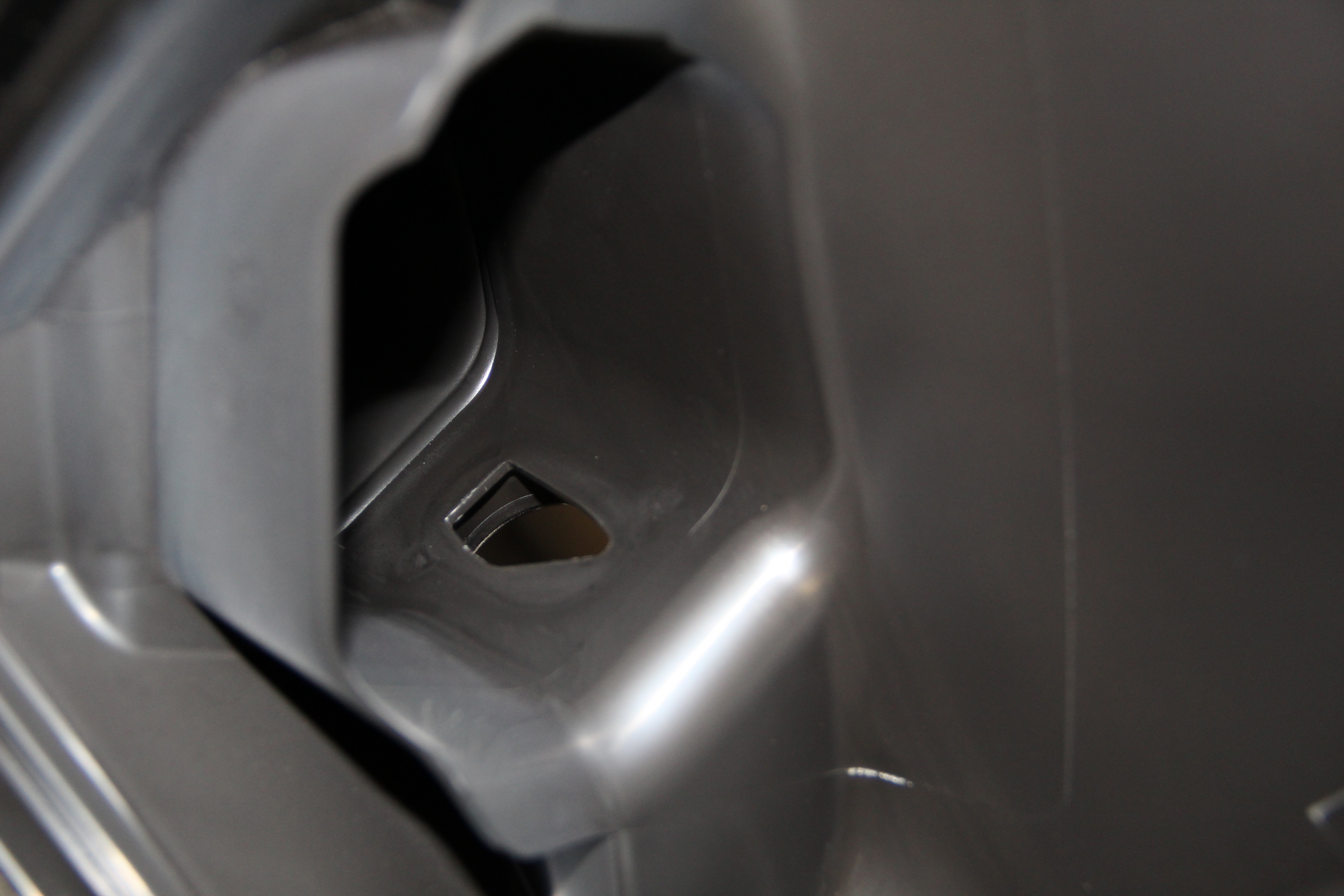
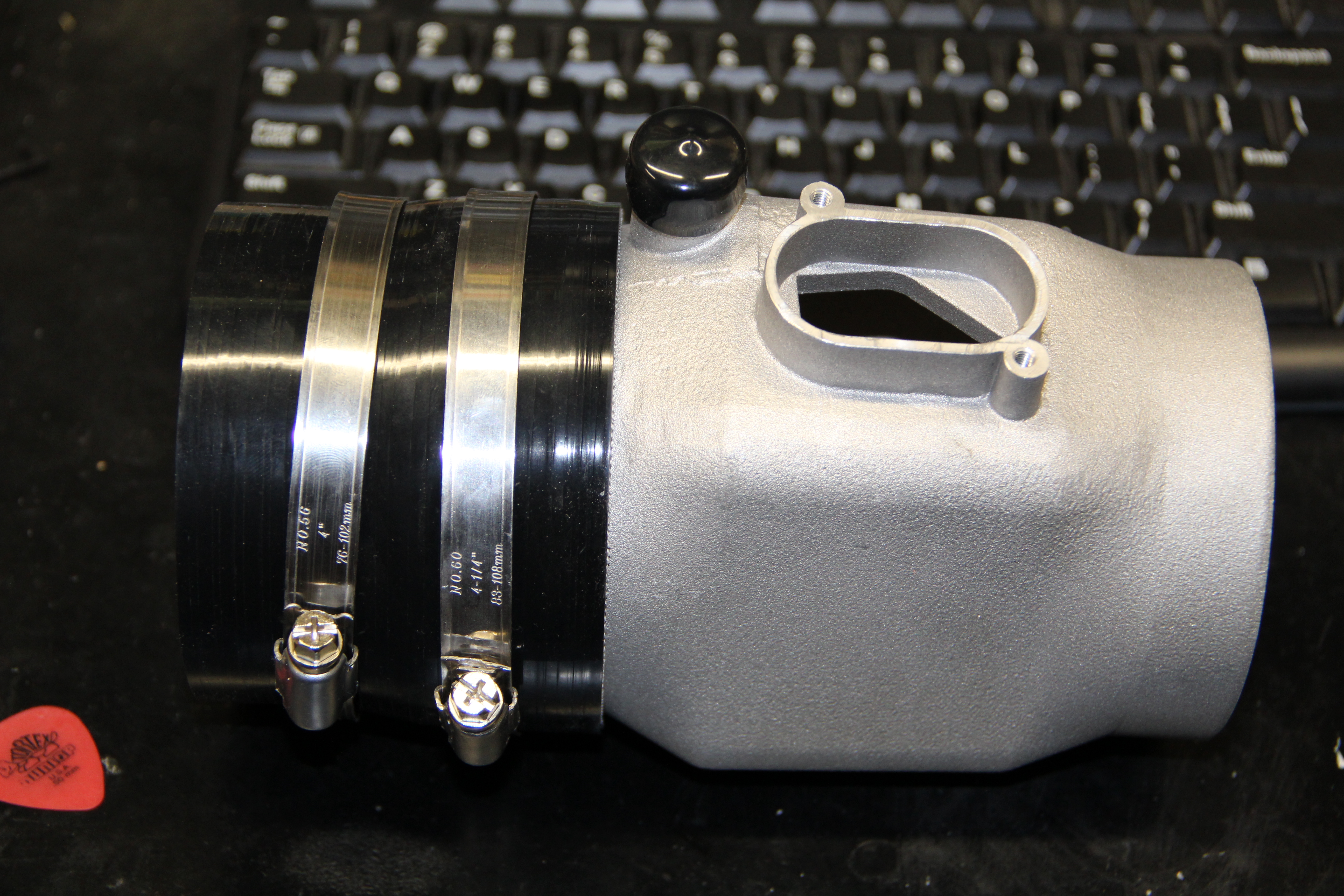
Here is a picture of the stock MAF housing cutout and the CTS MAF housing, they are pretty much identical so good news there.

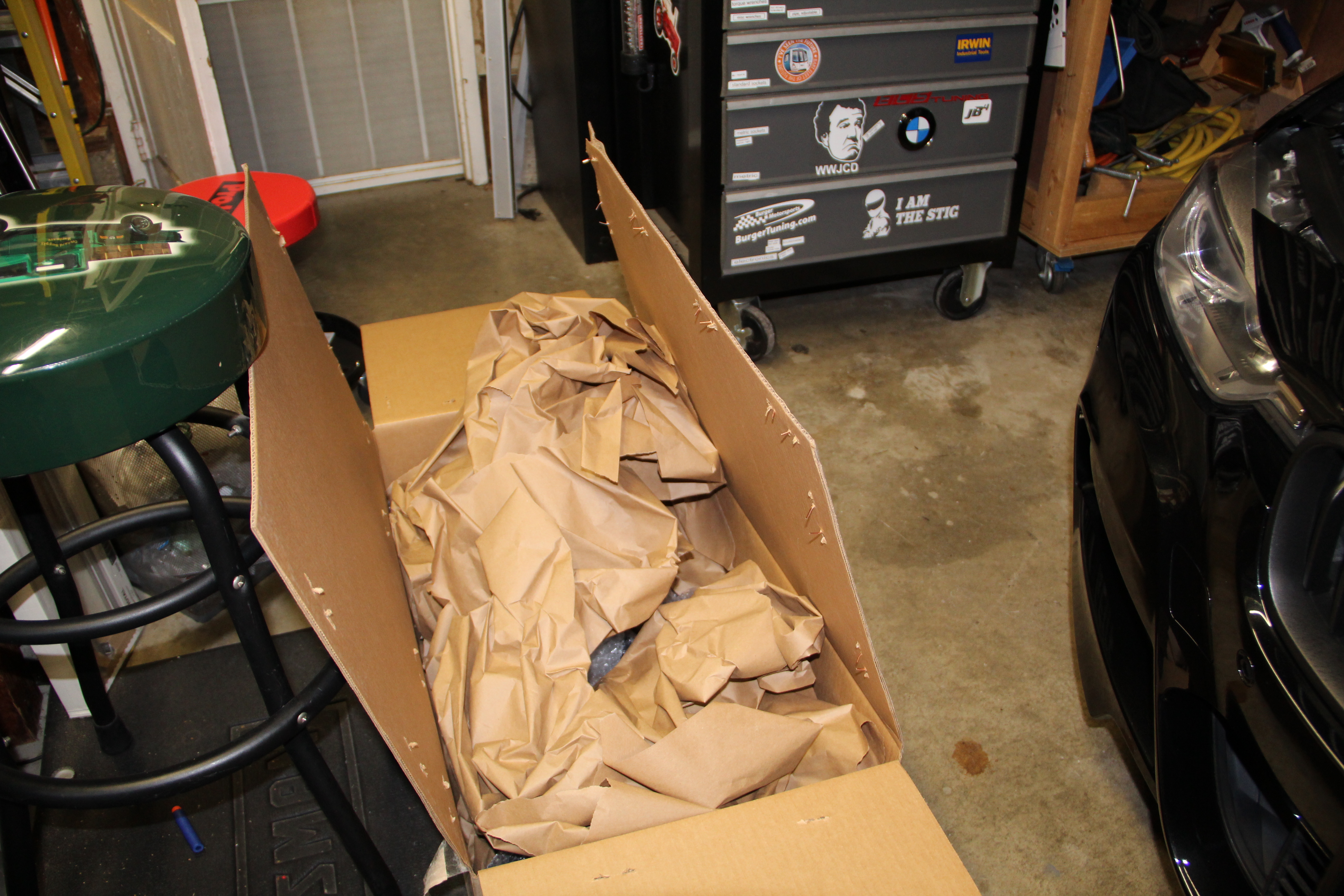
I ordered on a Friday and it was delivered on Thursday the following week. The box came well packaged, no complaints there.
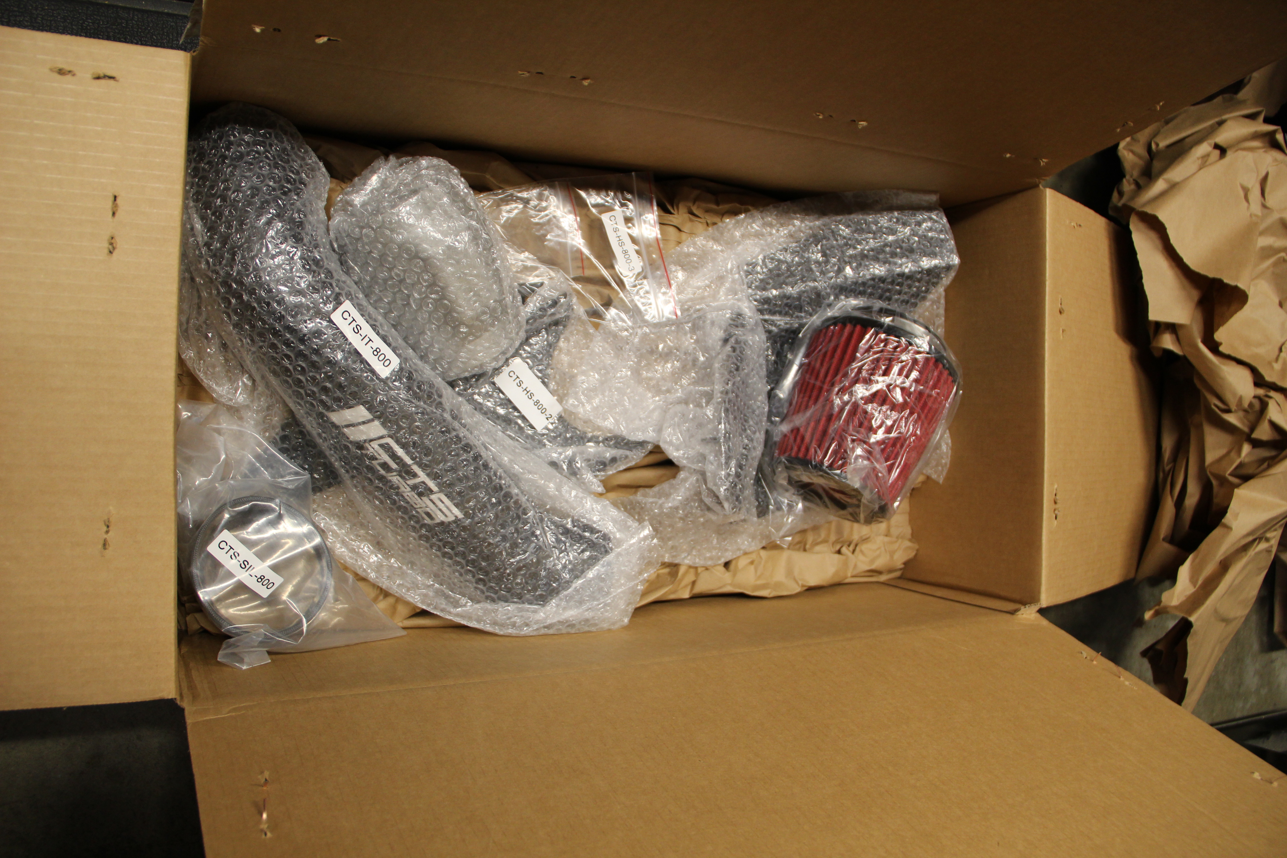

Upon further inspection there ARE NO INSTALLATION INSTRUCTIONS anywhere in the box or online. Now I know what you’re thinking, how hard can putting a tube together be, but let me tell you, there are a few components that need to be assembled and it’s not as straight forward as it may seem. I’m still not sure I installed this thing 100% correct. I’ve reached out to CTS for instructions, I’ll be sure to update this once I get them.
I spoke with CTS and they let me know the instructions would be up soon. They told me the test car is a daily driver and it’s hard to schedule a swap with the test car.
Installation:
Technical Skill
Cost
Time Commitment
PITA factor
Butt Dyno affect
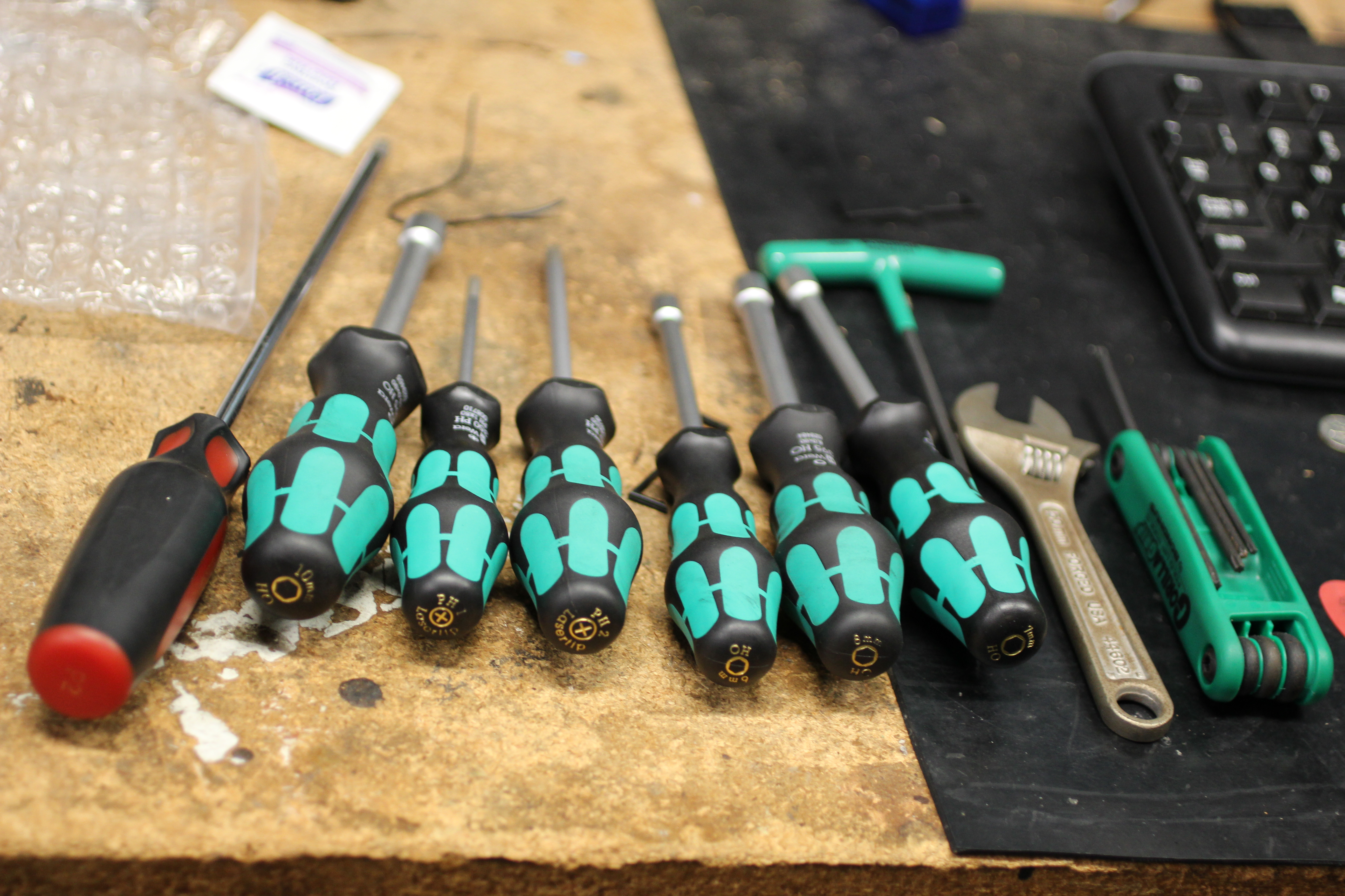
Tools I used to install:
- 6mm, 7mm, 8mm, 10mm nut drivers
- For various hose clamps, and fasteners. You will be able to use a Phillips screwdriver as well so all these nut drivers are not needed but I much rather prefer tightening hose clamps with a nut driver
- T15 Torx
- Needs to be somewhat short, for removing/installing MAF sensor, that T-Handle torx only worked on one screw as it was too long for the other
- Adjustable wrench (Nut driver, socket, anything to hold a nut will work)
- To put together the “heat shield” (that’s what I’m calling it)
- Just need something to hold the locking nuts as you assemble the intake
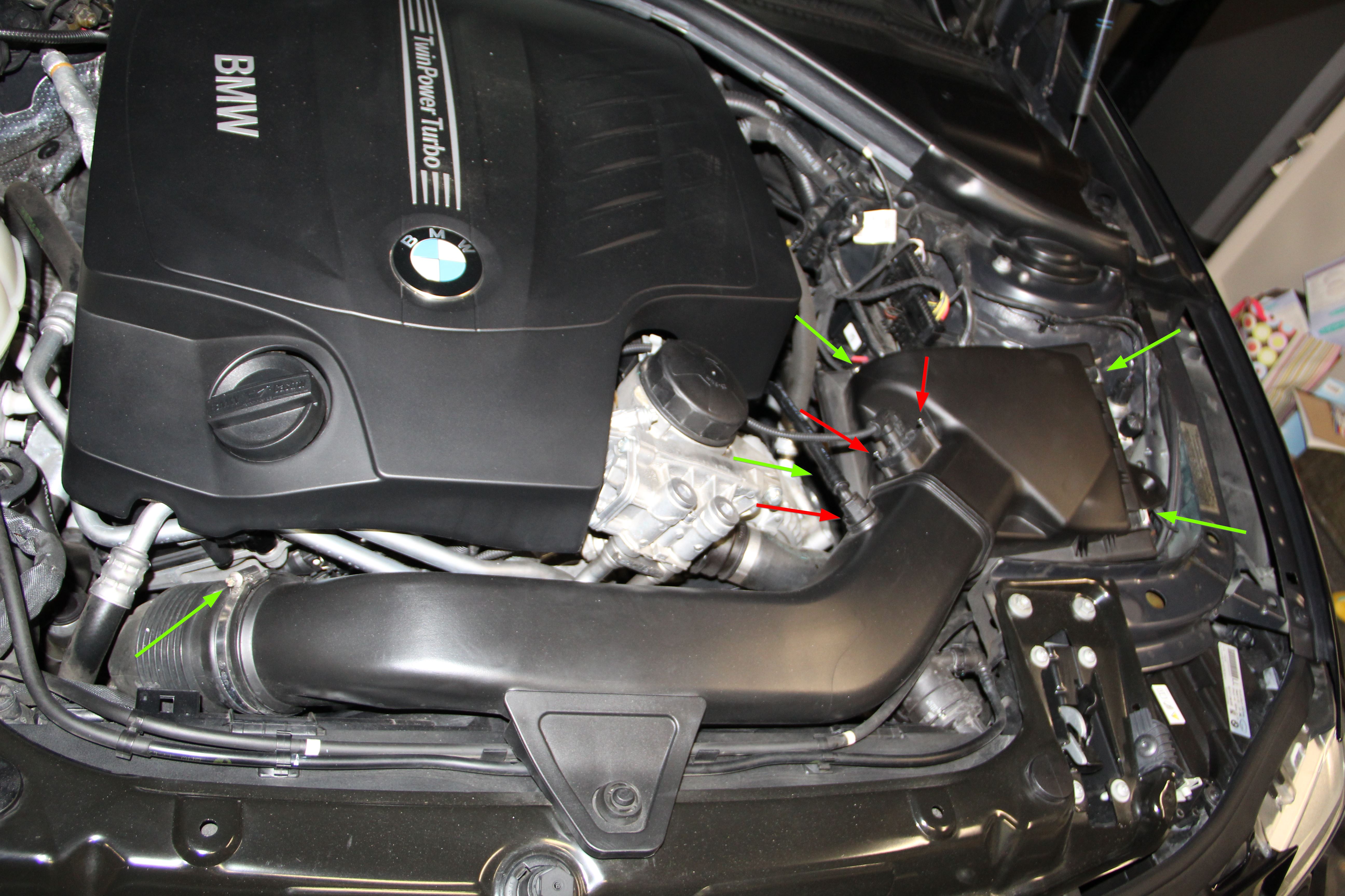
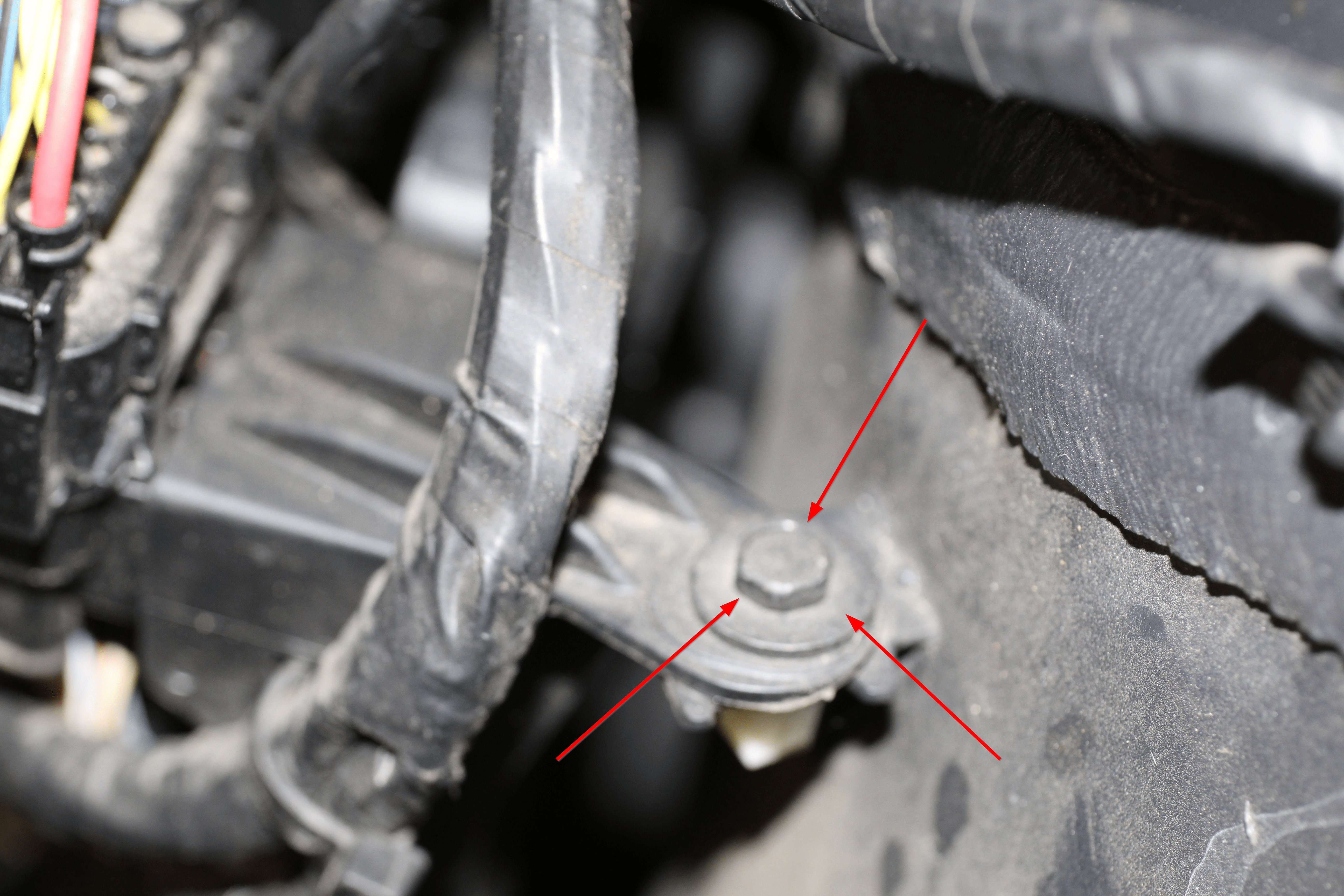
- Remove the MAF sensor and Vacuum line from the stock intake
- The Red arrows show what to remove, the MAF is held in by 2 T15 torx screws and the vacuum line in a PITA to get off, you need to squeeze the two tab things and pull gently. Careful it’s very fragile.
- The MAF sensor is also held in pretty tight, be gentle with it as there is a fragile exposed component on the outside of it.
- Put the MAF screws to the side, you will need them later
- The Red arrows show what to remove, the MAF is held in by 2 T15 torx screws and the vacuum line in a PITA to get off, you need to squeeze the two tab things and pull gently. Careful it’s very fragile.
- Loosen the hose clamp on the left side of the picture and unsnap the 4 intake box clips.
- Again, be careful with the intake box clips, they can fly off and go into the abyss of the engine bay

Stock intake removal, Red 1st, Green 2nd 
MAF housing and vacuum hose close up
- Again, be careful with the intake box clips, they can fly off and go into the abyss of the engine bay
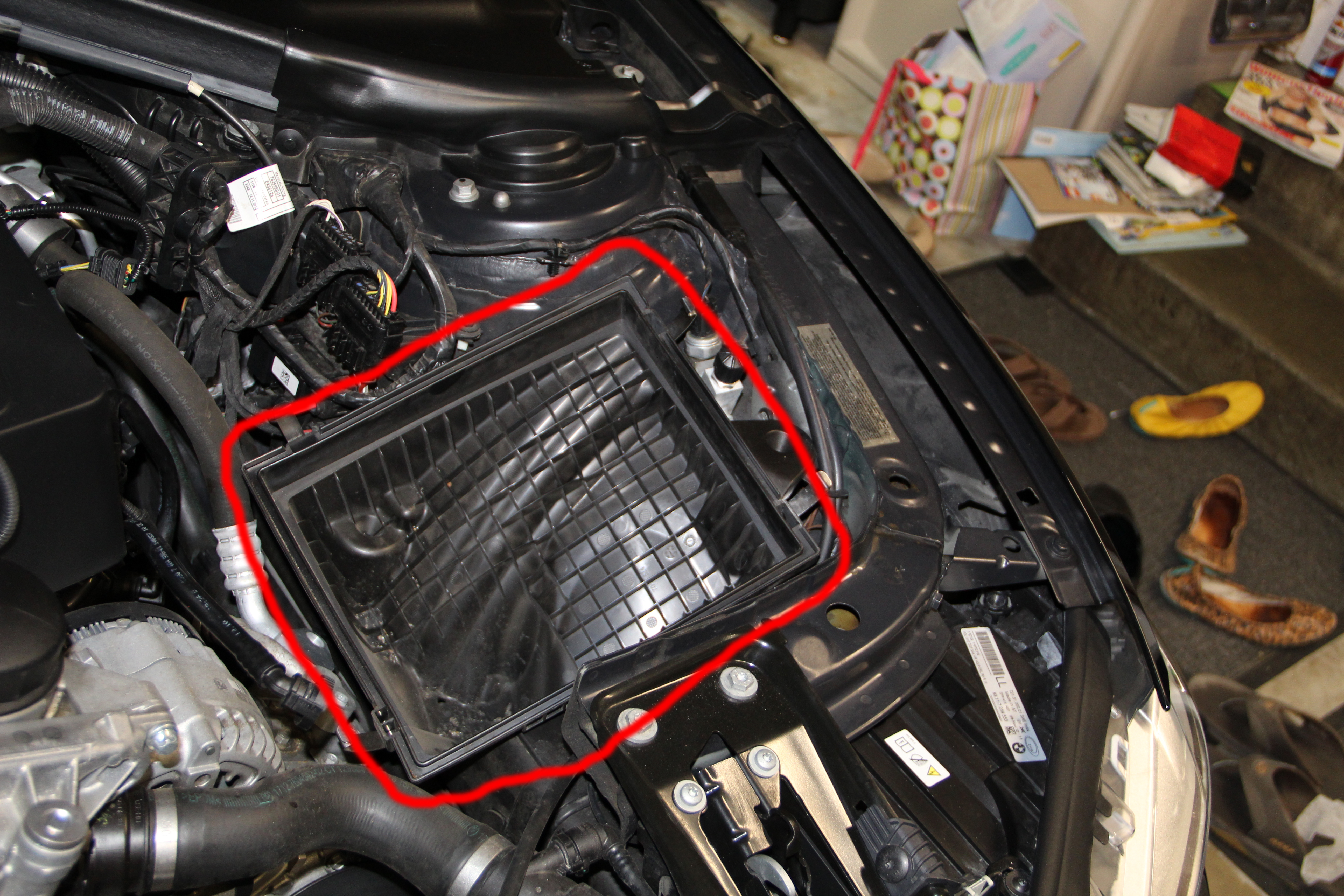
- Remove the lower part of the intake box by pulling up on it. It’s only held down by rubber grommet like things

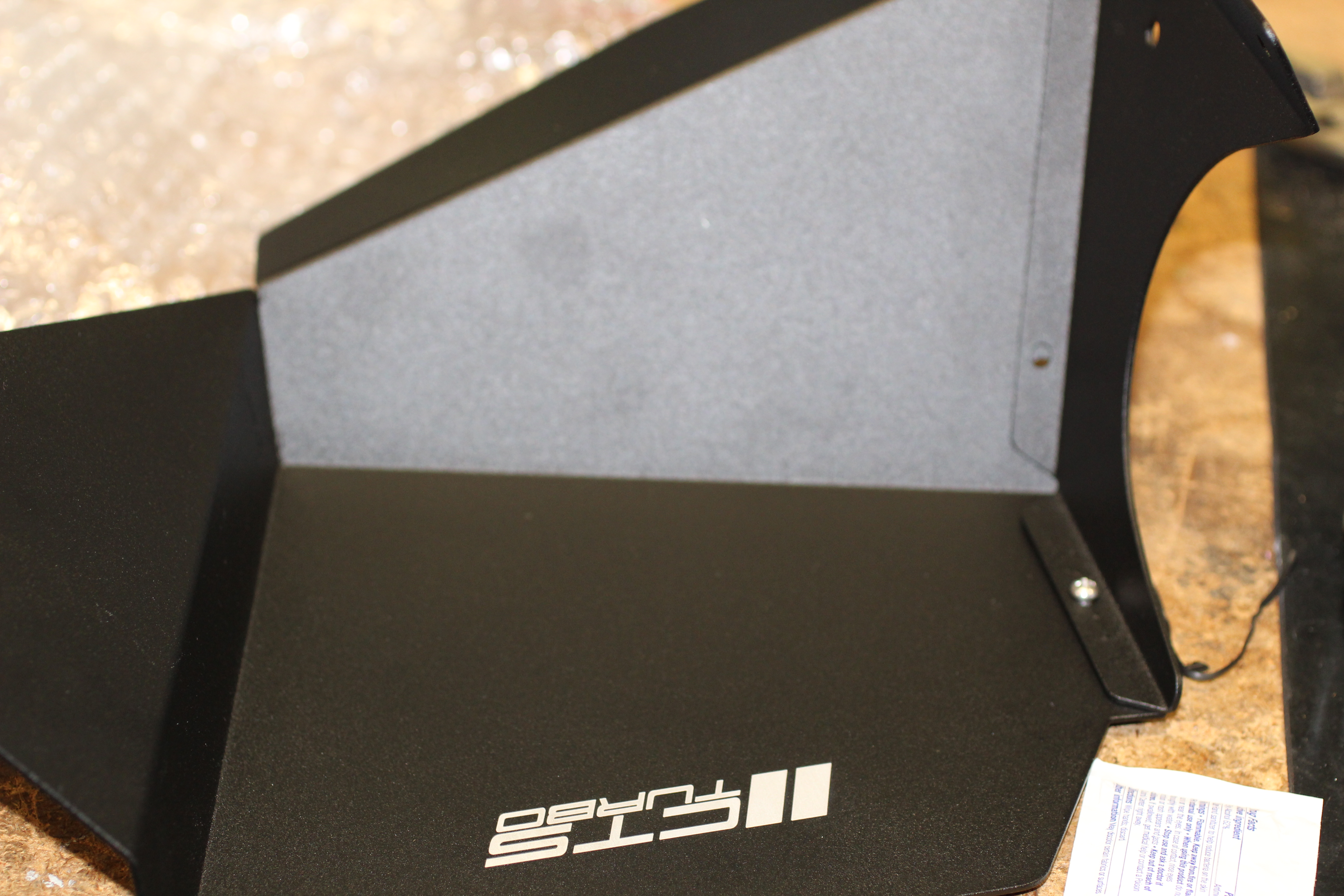
Lower intake box - Install the heat shield piece. This is where it get’s a little confusing. The heat shield comes in 2 parts, don’t be an idiot like me and assemble it incorrectly. The below picture is how NOT TO DO IT. The smaller piece on the right side should sit UNDER the larger piece, not over it as pictured.

WRONG WAY TO DO IT. THE SMALLER PIECE GOES UNDER THE LARGER PIECE. - Once you assemble these two pieces you need to place this in the area the original intake box was in. First you need to install the red circled piece below in the lower grommet of the original intake box

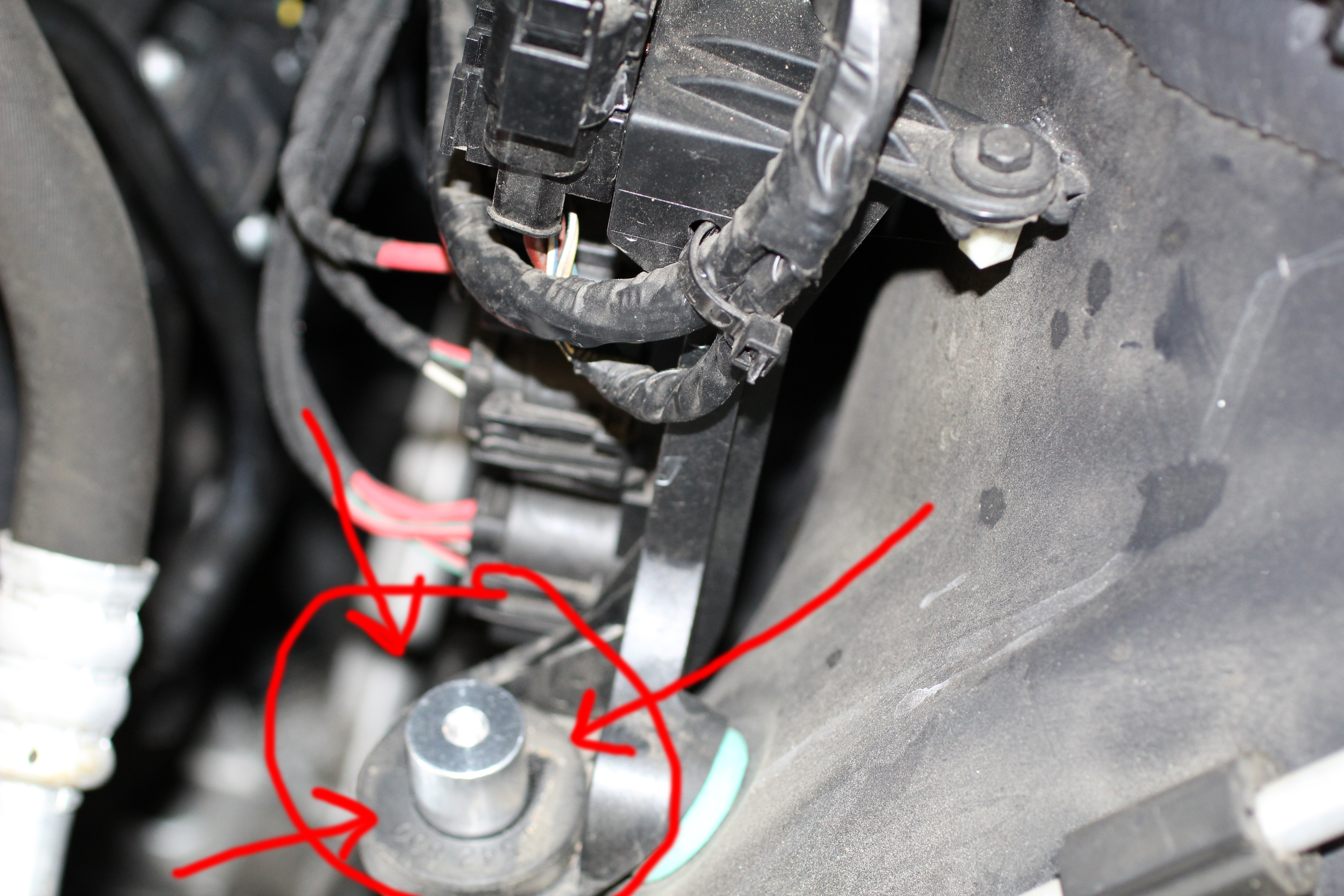
Install this piece by pushing it into the rubber grommet of the original airbox - You then need to remove the highlighted screw below to mount the heat shield.

- Use the supplied 10mm bolt on the bottom bracket and the removed original 7mm screw on the top bracket.
- This part is a major PITA. It’s very tight and hard to get to these areas, be prepared to swear a lot. I sure did.
- Once that is installed there is another oddly shaped bracket (kind of looks like a tuning fork and referred to as the “tuning fork” from here on out) that needs to be installed.
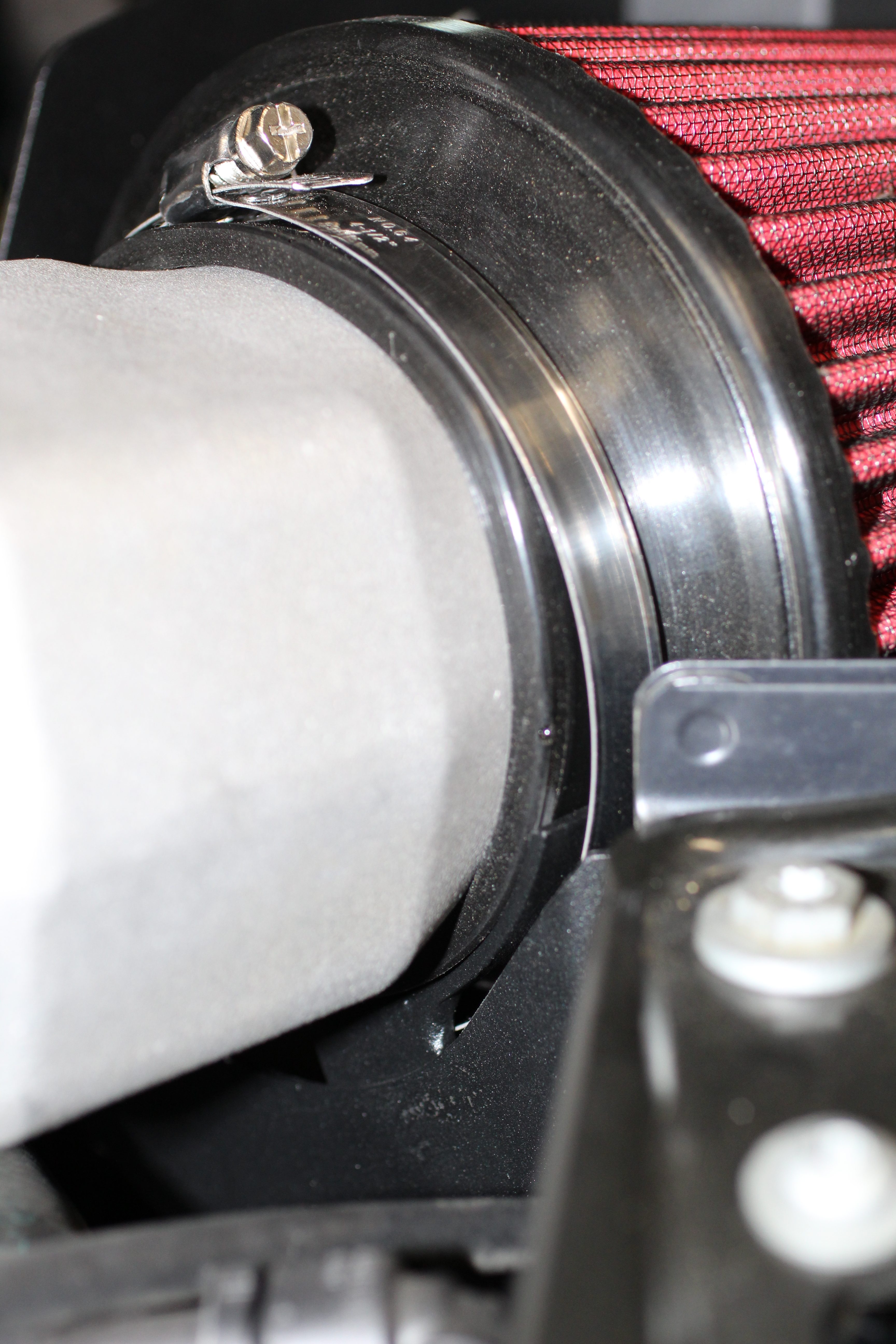
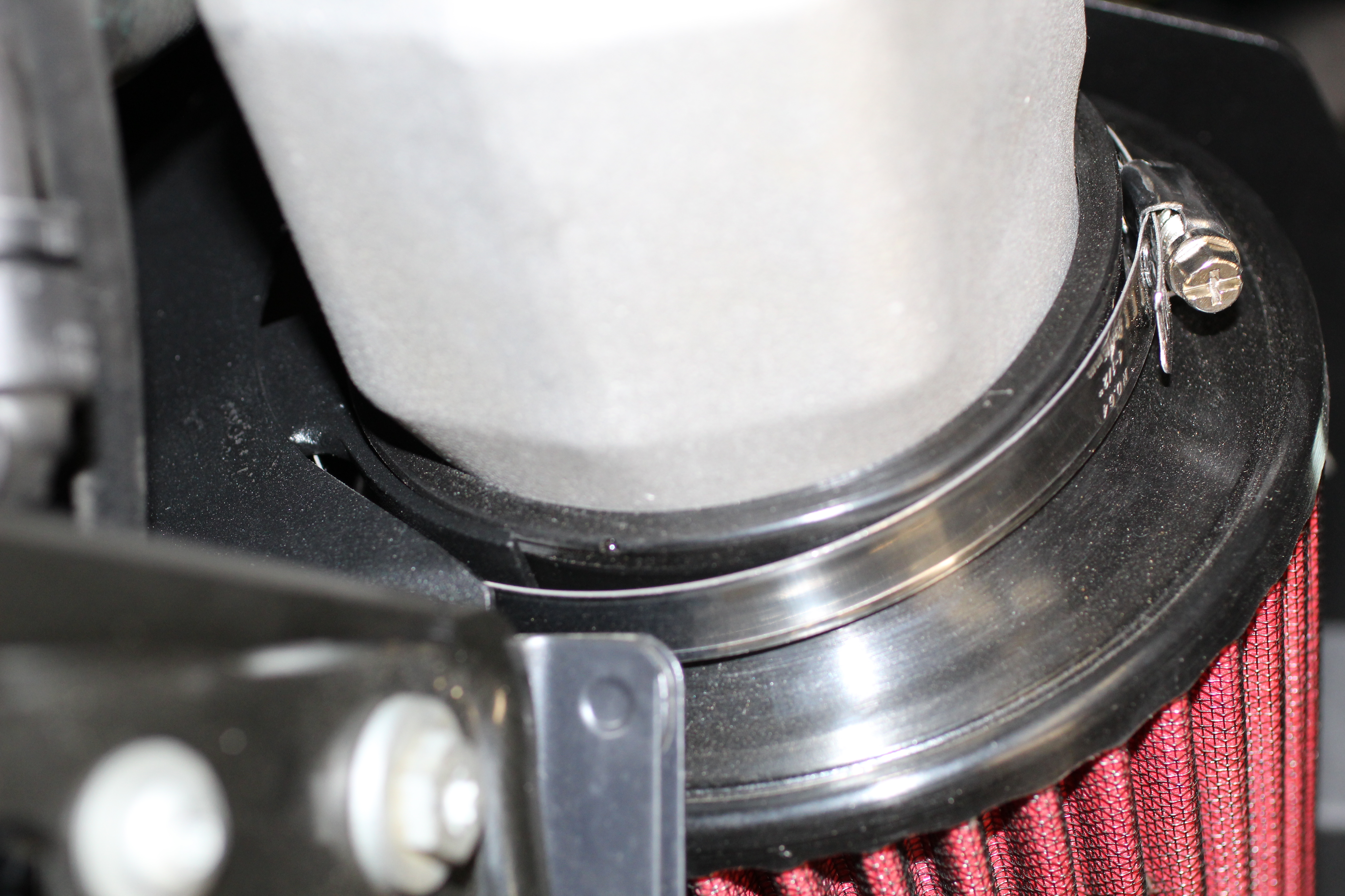
- The band clamp that sec
ures the air filter to the intake tube goes around both the air-filter and the “tuning fork” support bracket.
The black “tuning fork” bracket secured by a screw seen below the MAF housing. It kind of cradles the MAF housing. 
The hose clamp goes around both the air filter and the “tuning fork” 
Another shot of the hose clamp going around both the air filter and the support bracket.
- The band clamp that sec
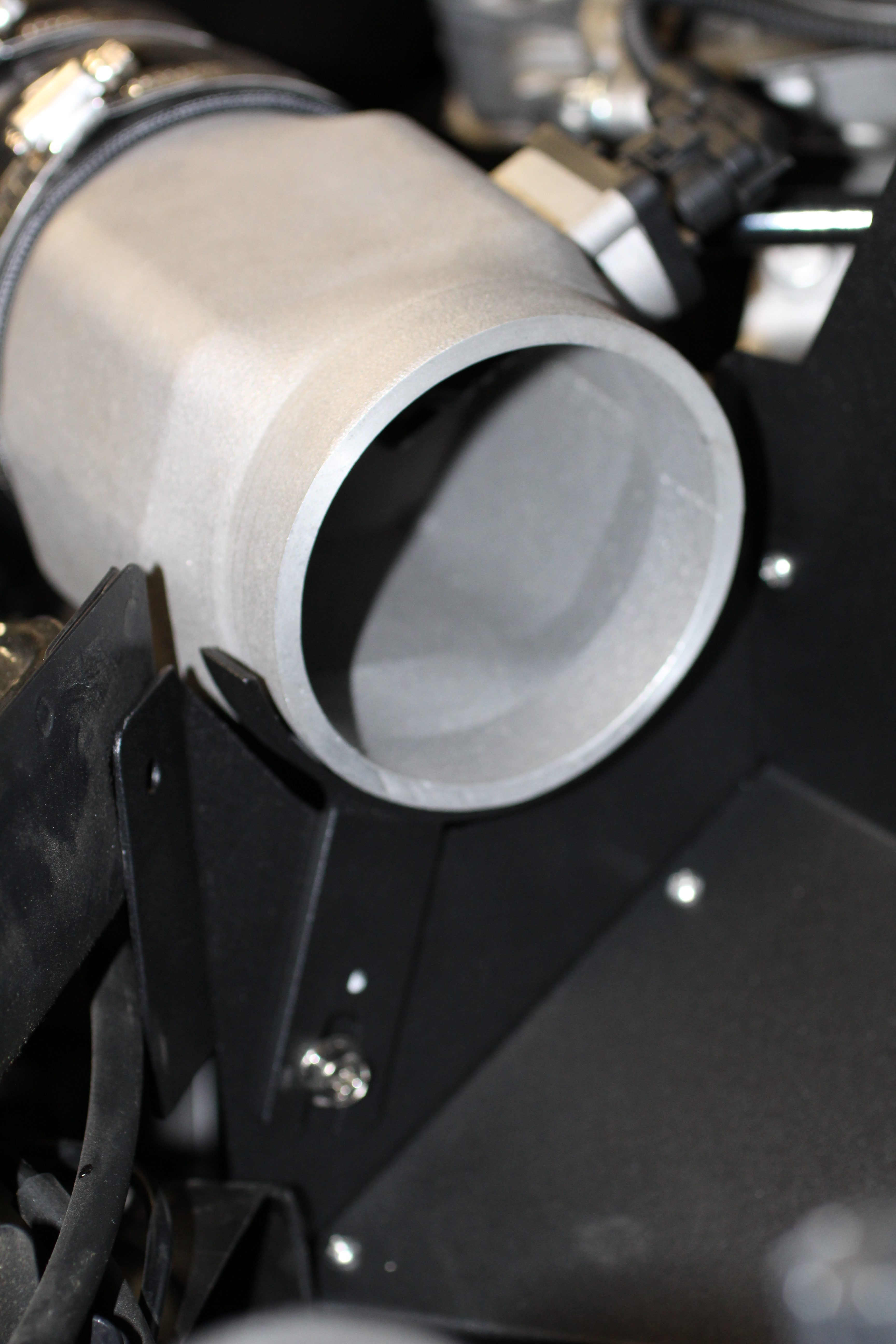
- Assemble the air intake, this is all very straightforward, I started with the MAF housing, then the tube, then the air filter.

MAF housing assembly - Install the vacuum line, the MAF sensor (be careful) position the MAF housing and air intake tubes so that everything is aligned and you should be good to go. I did have a few issues which are listed below.
Issues:
I had a few bolts left over, NO IDEA where they go.- After speaking with CTS I’m told these are extra’s in case some go missing in the engine bay
- The vacuum line does not sit perfectly flush in the vacuum hose fitting
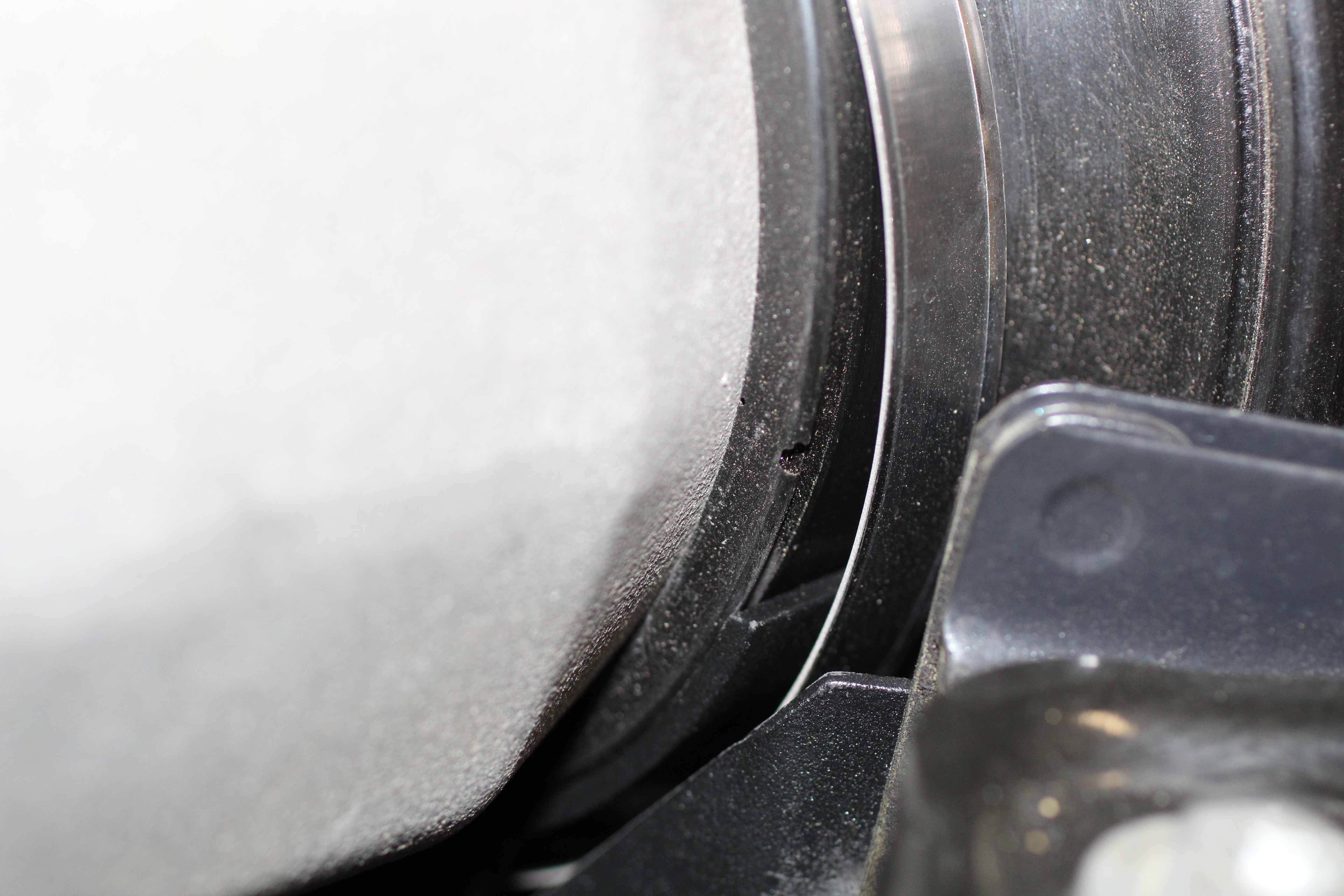
The air intake mounting hole for the rubber grommet will not snap in, no matter how hard I tried and re-positioned- After speaking with CTS they suggested using some sort of lubricant to get the grommet in. I tried using WD-40 per CTS’s advice but that didn’t work. I ended up using a combination of a small screw driver and WD-40.

 Lube and a small screwdriver, be gentle and you won’t hurt the grommet.
- The stock air funnel intake tube (Part 11 in the picture below) is in the way of the CTS heat shield. I’m not sure if that it suppose to be removed or not. It is a very weird fit with that part installed. I’m hoping that does not need to be removed as that would make it a MAJOR PITA for when the car goes in for routine maintenance and warranty work.

The intake is not very snug, it wobbles a bit more than I would like. Granted this is probably due to me installing it incorrectly. Will update this post if I find something fixes it.- This issue was fixed after properly securing the “tuning fork” bracket and rubber grommet.
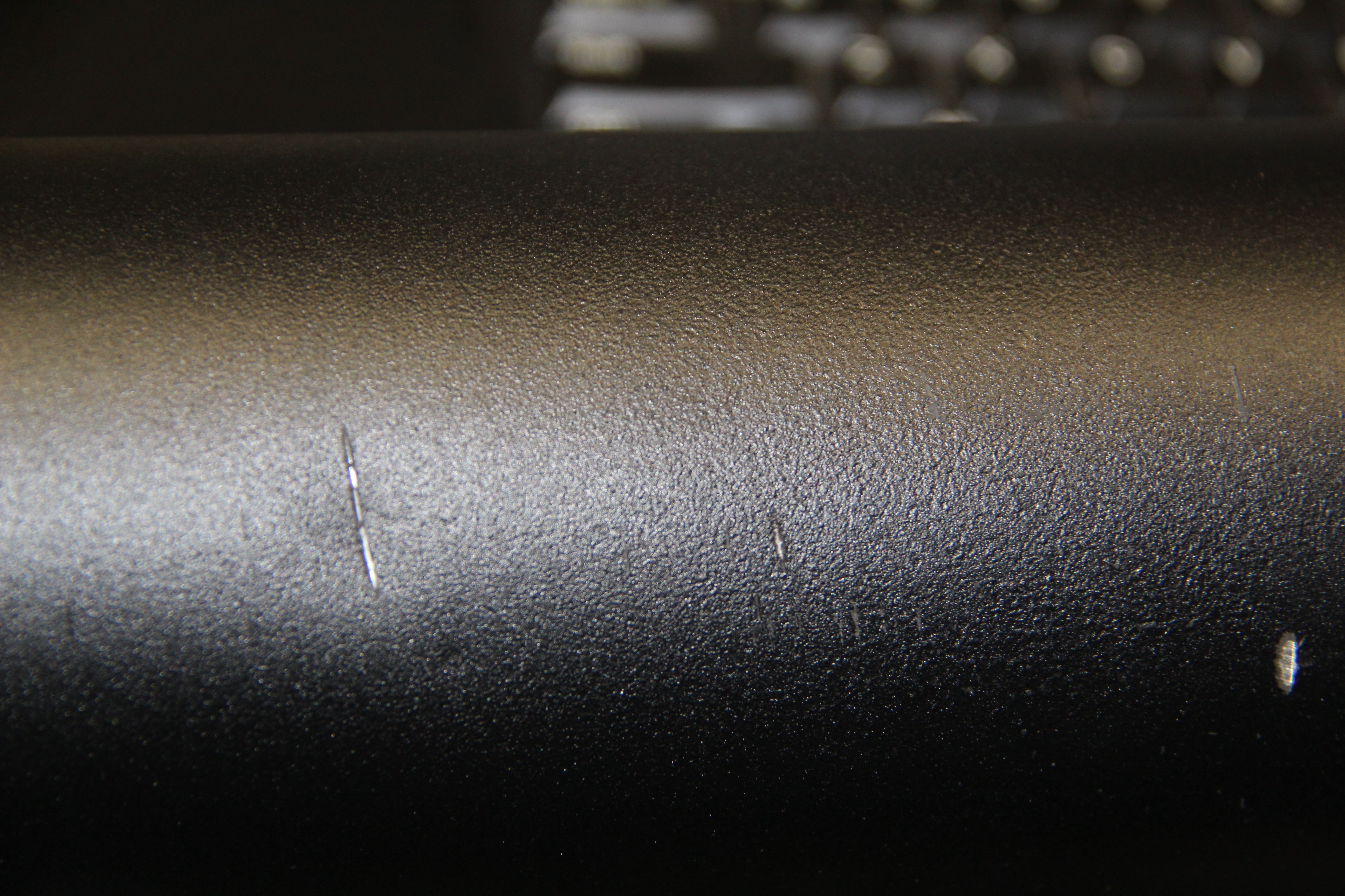
- There were a few gouges in the intake tube, not a huge deal but still.

Gouges from the factory, straight out of the box
Testing IAT (Updated 2/10/18)
Here’s the bottom line. IAT delta is more directly correlated to your intercoolers (FMIC) performance than it is the temperature of the air coming in through your intake.
Original text (7/23/16)
On the forums there is always some concern about how an intake that takes air in from the engine bay affects Intake Air Temperature (IAT.)
I decided to test this with both the stock and this CTS intake.
Also, someone brought up a great point about the cast aluminum MAF housing and it soaking up heat. (I plan to test this further when I have some time, check back soon)
Test method:
- Used a genuine Carly OBDII adaptor purchased on Amazon
- Used TorquePro for Android
- Setup TorquePro to log IAT and Ambient Temperature with both the stock intake and then the CTS intake
- Also logged GPS speed
- For both tests I let the car warm up for 20 minutes driving around, parked in the garage for about 10 minutes, and then took the same route in both cars.
- The trip consisted of local side streets for about 2 miles at around 25-35 MPH with many stop signs and stop lights, and then a quick blast down the freeway for about 2 miles, back to the side streets back to the house.
Note! The ambient air temp was different by 10-20º F
I NEED TO REDO THE TEST USING THE ABOVE METHOD.
If you take into account the ambient air temps, speed, etc… you can get sort of an idea of the change in IAT with this intake. I plan on redoing this test and logging shortly.
Hover over the chart for detailed info
[visualizer id=”359″]
[visualizer id=”384″]


I’ve also reached out to the developer of Torque to figure out how to get those numbers on the bottom into an understandable format. I cannot for the life of me figure out how to convert that to hh:mm or HH:MM or any sort of understandable time. I’ll update once the developer gets back to me. If anyone reading this knows, please reach out to me.
Some quick data I extrapolated.
Using the areas where my average speed was around 68MPH
Stock the ambient temp averaged 71.6F (22C) and the intake 100.4F (38C) a difference of 28.8F
CTS the ambient temp averaged 59F (15C) and the intake 77F (25C) a difference of 18F
Update on 9.29.16
I did some more logging last night and the difference between IAT and ambient temps were far more apart for some reason.
It was a normal Bay Area night, outside temps in the low 60’s F.
Below is the chart just cruising around.

Once again, I’m very unsure of the validity of this data so please take this with a grain of salt.
I would really be grateful if someone with knowledge and experience could chime in and validate or invalidate the significance and accuracy of this data. Also maybe even a little guidance on what to test and how.
Thanks!
Link to the discussion thread on Bimmerpost here